Last updated: June 25, 2026
Key Takeaways for AS9102-Compliant Inspection
-
Aerospace CNC inspection methods follow a structured eight-step workflow that aligns with AS9102 and AS9100D standards.
-
The sequence starts with drawing review and ballooning, then moves into material traceability verification and control plan development.
-
CMM-based dimensional and GD&T verification, combined with appropriate NDT methods, forms the core of compliance validation.
-
Complete documentation through AS9102 Forms 1–3, final traceability audits and release procedures creates audit-ready records.
-
Precision Advanced Manufacturing integrates this full workflow under AS9100D-certified systems. Request a quote to discuss aerospace CNC inspection needs.
Prerequisites for a Reliable FAI Workflow
Four core concepts create the foundation for a consistent aerospace CNC inspection workflow.
First Article Inspection (FAI): A formal, documented verification that a production process produces a part conforming to all engineering, design and specification requirements. AS9102 supports AS9100 by providing objective evidence that the production process has been validated before rate production begins.
Coordinate Measuring Machine (CMM): A precision metrology instrument that measures part geometry against nominal CAD data. CMM serves as the primary tool for GD&T verification on tight-tolerance aerospace components.
Control Plan: A documented matrix of inspection checkpoints, measurement methods, frequency and acceptance criteria tied to each critical characteristic on the drawing.
Special Processes: Operations such as heat treatment, NDT, welding, plating and surface coating that alter material properties and require certified process providers. AS9102 Rev C Form 2 requires documentation of all special processes, including certifications and NADCAP approvals.
These prerequisites create a shared language for inspection planning. The eight steps that follow turn AS9102 requirements into a practical shop-floor system that controls traceability, documentation and measurement risk from raw material through final release.
Step 1: Review Drawing and Balloon Every Characteristic
The workflow starts with a full drawing review that sets the scope for every later step. Every dimension, tolerance, note and specification receives a unique balloon number. This ballooning process creates a one-to-one map between the drawing and the inspection record.
Inputs: Released engineering drawing, applicable specifications and customer quality clauses.
Outputs: Ballooned drawing and a characteristic accountability log that feeds AS9102 Form 1.
AS9102 Rev C requires FAIRs to be tied to a specific drawing or model revision. The team confirms and records the revision level before any inspection activity begins. GD&T callouts such as flatness, true position, perpendicularity and profile are flagged for CMM measurement in Step 4.
Step 2: Verify Material Traceability and Certifications
Material traceability protects aerospace programs from hidden material risk. Each raw material lot links to a certified mill test report or material certification that confirms alloy, temper, heat or lot number and compliance with the applicable material specification.
Under AS9100D, traceability must remain intact throughout the production process. The heat or lot number recorded at receiving flows through to the finished part record and the FAIR. Any break in that chain becomes a nonconformance.
Confirming the material specification matches the drawing callout prevents common material errors such as the correct alloy in the wrong temper. Once the specification is verified, the certification must come from an approved source to avoid traceability breaks during AS9100D audits. Logging the heat or lot number in both the job traveler and FAI package creates a permanent documentary link from receiving through final inspection.
With material traceability established, the next step defines how and when those traceable parts will be inspected during production through a control plan that governs every measurement from first article through rate production.
Step 3: Build the Control Plan and In-Process Checks
The control plan turns drawing requirements into a production-floor inspection schedule. It defines which characteristics are measured, at what frequency, with which instrument and against what acceptance criteria.
The control plan identifies features that require CMM measurement, so CMM programs are developed and proven at this stage. Once the CMM program is validated, the team defines first-article triggers based on the control plan risk assessment and communicates them to the machining team so operators know when to stop and call for inspection.
Decision points include identifying critical and key characteristics that require 100 percent inspection versus statistical sampling. The team also confirms that all measurement equipment is calibrated. Measurement equipment used for FAI must be calibrated and provide accuracy at least 10 times the required tolerance, and Gauge R&R studies are recommended.
Step 4: Perform Dimensional and GD&T Verification
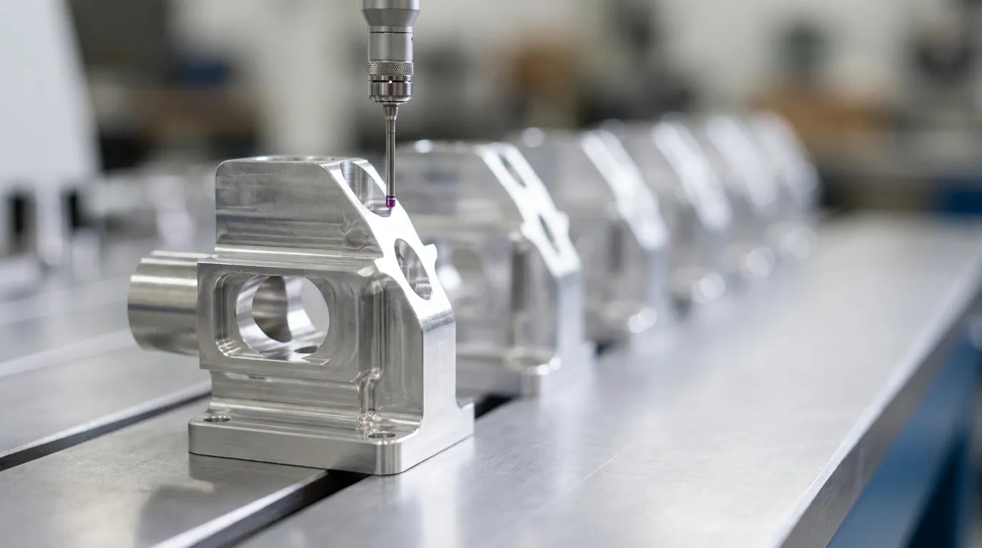
Dimensional verification forms the core of the inspection workflow. CMM is the preferred method for complex GD&T callouts because it captures three-dimensional geometry against nominal CAD data with strong repeatability.
Conventional metrology tools such as micrometers, calipers, height gauges and optical comparators supplement CMM for straightforward linear dimensions and surface checks. Each measurement is recorded against the ballooned characteristic, with the actual value, nominal and tolerance documented.
GD&T verification requires the CMM program to reference the correct datum structure as defined on the drawing. Datum errors propagate through every downstream measurement, so incorrect datum feature simulator setup becomes a common source of nonconformance. Confirming datum feature simulators are correctly configured before running the program prevents false accepts that create field risk and false rejects that delay production.
Precision Advanced Manufacturing operates under AS9100D-certified quality systems with in-house CMM capability and delivers validated dimensional data as part of every inspection package. Discuss GD&T verification and CMM programming requirements with the team.
Step 5: Select and Execute NDT Methods
Non-destructive testing detects internal and surface anomalies without compromising the part. Method selection depends on material type, geometry, defect type of concern and drawing or specification requirements.
AS9102 Rev C Form 2 requires NDT to be documented as a special process, with applicable certifications and process records included in the FAI package. NDT personnel must hold current certifications to the applicable level for the method being performed. AS9102 Rev C Form 2 requires NDT to be documented as a special process, and the full scope of Form 2 special process documentation appears in Step 6.
Step 6: Document Special Processes and Certifications
Special processes alter the material or surface condition of the part in ways that post-process inspection alone cannot fully verify. Heat treatment changes internal grain structure, plating affects corrosion resistance and welding creates metallurgical bonds that determine structural integrity.
Because these changes remain invisible to dimensional measurement, AS9100D requires that special processes be performed only by approved providers with validated process controls. Common aerospace special processes include anodizing, passivation, plating, heat treatment and welding.
Lockheed Martin supplier requirements make the consequence explicit, as use of unapproved processors causes FAI rejection regardless of whether the process itself was performed correctly. Suppliers confirm processor approval status before releasing parts to any special process operation.
Each process certification is collected, reviewed for conformance to the applicable specification and attached to the FAI package before Form 2 is closed.
Step 7: Complete First Article Inspection Report Forms 1–3
The FAIR consolidates all inspection evidence into three AS9102 forms that function as a single documentation system.
Form 1 (Part Number Accountability): Identifies the part, drawing revision and FAI scope. Child part FAIs are referenced here when applicable.
Form 2 (Product Accountability): Documents materials, special processes, functional test results and all associated certifications.
Form 3 (Characteristic Accountability): Records every ballooned characteristic with actual measured values, tolerances and inspection method.
A full FAI is required at initial production of a new part number and again when defined triggers occur, such as design changes affecting fit, form, function, safety or reliability, or changes in manufacturing source, process or method. AS9102 Rev C distinguishes full FAI from partial FAI, with partial FAI limited to affected characteristics and referencing the prior full FAI.
Completing the forms closes documentation entry, but the workflow still requires verification and traceability checks before shipment. Step 8 addresses that final review.
Step 8: Run Final Review, Traceability Audit and Release
The final review confirms that every element of the FAI package is complete, legible and traceable before parts are released for shipment.
The traceability audit verifies that the material heat or lot number on the certification matches the job traveler, the traveler matches Form 2 and Form 2 references the correct drawing revision on Form 1. Any gap in this chain is resolved before release.
FAI reports must be submitted to the customer no less than five working days prior to the shipment date when source inspection is not required. Early submission allows the customer quality representative to review and accept the FAIR without delaying delivery.
Precision Advanced Manufacturing’s AS9100D-certified quality system integrates traceability, documentation and final release controls into every production program. Start the conversation about an upcoming program’s inspection and compliance needs.
Common Workflow Challenges and Practical Fixes
Even well-structured workflows encounter nonconformances, often at handoff points where information moves between systems or people.
Datum reference errors on CMM occur when datum feature simulator setup does not match the drawing. Verifying datum structure against the drawing before running the CMM program and performing a first-piece check with a second operator catches these errors before they affect the full dataset.
Material certification gaps represent a breakdown at the receiving-to-production handoff when heat or lot traceability is missing. A receiving inspection hold until a conforming certification is obtained and logged prevents this gap from reaching the shop floor.
Special process certification issues arise when supplier qualification controls fall short. An approved processor list and verification of approval status before releasing work orders keep expired or unapproved processors out of the workflow.
FAI scope errors occur when partial FAI is applied where full FAI is required because teams misread AS9102 Rev C triggers or overlook customer clauses. A structured contract review at program launch, with documented FAI scope and customer concurrence when ambiguous, prevents these issues.
Out-of-tolerance dimensions on first article signal that process capability was not established before FAI. Capability studies on critical features during process development, followed by tooling or feed adjustments, stabilize the process before the formal FAI event.
Frequently Asked Questions
When is a full FAI required versus a partial FAI under AS9102 Rev C?
A full FAI is required at initial production of a new part number. It is also required when changes affect fit, form, function, safety or reliability, or when the manufacturing source, process, site or tooling changes in a way that makes the prior FAI nonrepresentative. A partial FAI covers only the characteristics affected by a defined change and references the baseline full FAI. Customer quality clauses may impose stricter requirements, including a full FAI at every drawing revision, so teams review contract requirements at program launch to determine the applicable scope.
What triggers a new full FAI after a production lapse?
AS9102 Rev C and most customer quality plans define a maximum production lapse period after which a new full FAI is required to re-establish process capability and traceability. The specific duration appears in the standard’s referenced guidance or in the customer contract. Programs resuming after an extended gap confirm the applicable lapse threshold with the customer before restarting production to avoid a shipment hold.
How does GD&T verification on a CMM differ from conventional measurement?
CMM measures three-dimensional geometry by probing multiple points on a surface and computing the relationship between features relative to the datum reference frame defined on the drawing. This approach allows direct verification of GD&T callouts such as true position, profile of a surface and perpendicularity. Conventional tools like micrometers and calipers measure linear distances and work well for straightforward dimensional checks but cannot directly evaluate complex GD&T relationships without additional fixturing or calculation. For tight-tolerance aerospace parts, CMM serves as the preferred method for any characteristic with a GD&T callout.
How should NDT method selection be documented in the FAI package?
NDT method selection follows the drawing, applicable material specification and any customer-imposed NDT requirements. The selected method, applicable procedure, personnel certification level and acceptance criteria appear on AS9102 Form 2 as a special process. The NDT report or certificate of conformance is attached as supporting evidence. When the drawing does not specify an NDT method but the part geometry or material warrants inspection, the supplier documents the selection rationale and obtains customer concurrence before the FAI event.
How does a supplier maintain traceability when transitioning from prototype to full-rate production?
Traceability continuity from prototype to full-rate production requires that the material heat or lot number, process certifications and inspection records established during the FAI remain linked to the production configuration. Any change in material source, special process provider or manufacturing method during the transition is evaluated against AS9102 FAI trigger criteria. When a trigger is met, a new FAI or delta FAI is completed before production parts ship. A configuration-controlled job traveler that references the active drawing revision and FAI record at every production step provides a reliable method for preserving traceability across the transition.
Conclusion: A Repeatable Path to AS9102 Compliance
A standardized eight-step aerospace CNC inspection workflow, from drawing review and material traceability through CMM verification, NDT execution and FAIR completion, closes the compliance gaps that create program risk and inspection burden. Each step produces documented evidence that ties directly to AS9102 Forms 1 through 3, giving procurement managers, supplier quality engineers and program managers a repeatable, auditable process across every production run.
Precision Advanced Manufacturing delivers this workflow as an integrated capability under AS9100D and ITAR-compliant quality systems, with in-house CNC machining, metrology and finishing that reduce supplier handoffs and protect program timelines. Start a conversation about aerospace CNC machining and inspection requirements.