Last updated: April 17, 2026
Key Takeaways
- Spacecraft CNC machining relies on certified materials like Ti-6Al-4V and Invar with full heat-lot traceability for thermal stability and outgassing compliance.
- Five-axis machining and high-speed machining techniques create complex geometries with ±0.001″ tolerances, cut setups by 60–80%, and reduce thermal distortion.
- Rigid fixturing, vibration control, and thermal management protect thin-walled structures from defects under launch and in-orbit loads.
- Post-processing uses vacuum-compatible treatments, passivation, and laser marking with complete AS9100D documentation for full traceability.
- Partner with Precision Advanced Manufacturing for AS9100D/ITAR-compliant spacecraft components with zero-defect yields and scalable production.
11 Proven CNC Best Practices for Spacecraft Structural Components
1. Material Selection and Certification for Space Environments
Spacecraft environments require materials with verified outgassing behavior and stable performance across extreme temperatures. Aerospace CNC machining requires full material traceability to mill sources and heat-treatment lots, including mill test certificates (MTC), heat-lot traceability, chemical composition, mechanical testing, and conformance to AMS, ASTM, or MIL specifications. Primary materials include Ti-6Al-4V for high-strength applications, 7075 aluminum for lightweight structures, and Invar alloy for thermal stability. Each material batch must carry complete documentation from melt source through final certification so engineers can trace any issue back to its origin.
2. Design for Manufacturability (DFM) in Thin-Walled Spacecraft Parts
Thin-walled spacecraft structures need DFM choices that protect dimensional stability and simplify machining. Minimum wall thickness should be 0.020″ for vibration resistance, with constant wall thickness wherever the design allows. This consistency reduces stress concentrations and makes toolpaths more predictable. Topology optimization then removes non-critical mass while preserving load paths for launch and in-orbit conditions. Designers should also avoid unsupported thin features that can deflect during machining, since even small deflection can push parts out of tolerance.
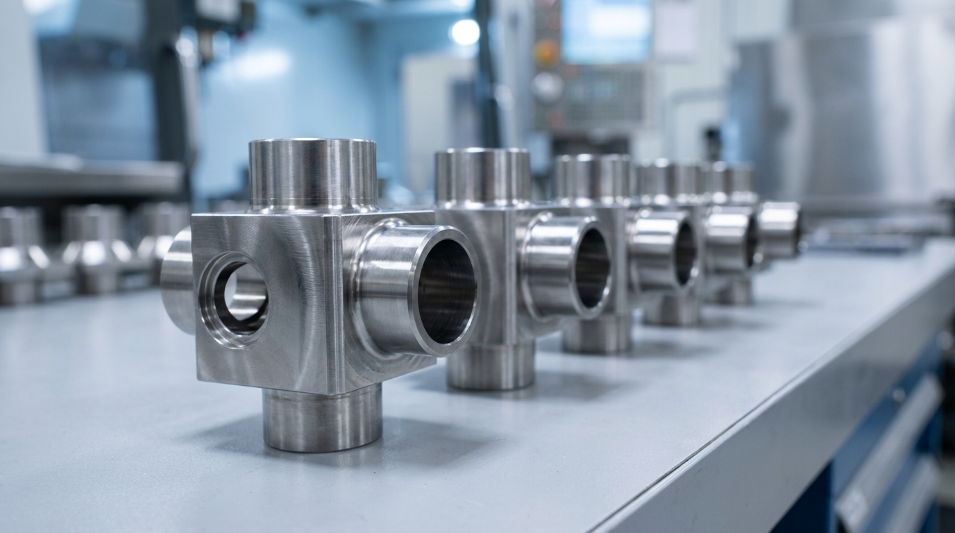
3. Advanced 5-Axis Toolpath Programming for Complex Geometries
Five-axis CNC machining enables higher feed rates and deeper cuts, reducing overall machining time by 40–50% for complex parts. It also cuts setup counts dramatically by allowing access to multiple faces in one clamping. Five-axis CNC machining reduces setup requirements by 60–80% for complex geometries, allowing parts to be machined in a single setup compared to 5–10 setups in traditional three-axis machining. Simultaneous 5-axis coordination maintains consistent chip load and delivers superior surface finishes on contoured features. Advanced CAM software manages collision detection and refines toolpaths so material removal stays efficient and predictable.
4. High-Speed Machining (HSM) Strategies for Aluminum Structures
Aluminum spacecraft structures respond well to high-speed machining when parameters stay within a controlled window. HSM techniques typically run at 10,000+ RPM with tuned feed rates that keep chip load consistent. Cryogenic coolants can extend tool life by up to 50% while preserving surface quality on long cycles. Light axial depths of cut paired with high feed rates limit heat buildup and reduce thermal distortion in thin sections. Reliable chip evacuation prevents recutting and surface contamination, which is critical for vacuum-facing surfaces.
5. Precision Fixturing Systems for Launch-Ready Parts
AT-Machining recommends ensuring rigid fixturing and minimal overhang to prevent vibration and deflection, which degrade accuracy in aerospace CNC machining. Vacuum chucks provide uniform clamping pressure while avoiding localized stress that can warp thin walls. Thermal-stable fixturing materials help maintain geometry as temperatures change during long machining cycles. Custom fixtures should also account for the thermal expansion coefficient of the workpiece so alignment stays consistent from roughing through finishing.
6. Thermal Management and Distortion Control During Machining
Spacecraft components must hold their shape across extreme hot and cold conditions, starting at the machining stage. Invar Alloy 36 provides an extremely low coefficient of thermal expansion, providing high dimensional stability under thermal cycling. In-process temperature monitoring and adaptive cooling strategies keep part temperatures within a narrow band. Low-heat cutting tools and tuned speeds and feeds further limit thermal input into the workpiece. These controls reduce residual stress and help parts stay within tolerance after they leave the machine.
7. Ultra-Precision Tolerance Control for Structural Interfaces
Structural brackets, flight controls, and engine housings in aerospace CNC machining have tolerance ranges of ±0.005 in – ±0.001 in, with demanding surface finish requirements. For specialized alloy parts that need even tighter control, advanced CNC machining techniques including 4-axis and 5-axis milling achieve tolerances as small as 0.0005 inches (±0.0005″) on specialized alloy parts. This tighter band represents the upper end of precision capability for many spacecraft structures. Coordinate measuring machines (CMMs) with environmental controls verify that features meet these tolerances. GD&T practices then ensure parts assemble correctly and carry loads as intended.
8. Vibration Suppression and Dynamic Balancing for Space Loads
Launch vibrations and orbital dynamics demand components with strong dynamic stability. Chatter suppression through tuned spindle speeds and appropriate tool geometry protects surface finish and dimensional accuracy. Shorter, more rigid cutting tools in five-axis CNC machining maintain optimal angles to reduce vibration and chatter, producing superior surface finishes. Dynamic balancing of rotating components then supports smooth operation in zero-gravity and during attitude changes.
9. Post-Processing and Surface Treatment for Vacuum Service
Spacecraft surfaces need specific treatments to perform reliably in vacuum and under thermal cycling. Aerospace CNC machining process includes post-processing surface finishing and treatments such as polishing, anodising, and protective coatings to enhance durability and corrosion resistance in extreme environments. Laser marking provides permanent identification while preserving structural integrity. Deburring and passivation remove burrs and contamination sources that could outgas or create stress risers in service.
10. Comprehensive Traceability and Documentation for Flight Hardware
AS9100D quality management standard requires strict material traceability in aerospace CNC machining, including heat-lot identifiers, certifications, and test reports maintained for every component throughout its lifecycle. Part serialization assigns unique serial numbers to each part via direct part marking (DPM) methods such as laser marking, dot peening, or 2D DataMatrix codes, which remain readable after post-processing. Digital threads then connect material certificates, process records, and final inspection reports. This complete record supports audits, failure analysis, and configuration control across the life of the spacecraft.
11. Scalable Production Validation for Spacecraft Programs
Transitioning from prototype to production requires processes that stay stable as volumes increase. AS9102 standard governs first-article inspection (FAI) in aerospace manufacturing environments, including CNC machining for spacecraft structural parts. FAI confirms that the process, not just a single part, meets requirements. Multi-shift capability with consistent quality metrics then supports production scaling. Process monitoring with embedded sensors enables real-time quality control and predictive maintenance so output stays reliable.
Implementing these 11 best practices requires deep technical expertise along with the right infrastructure, certifications, and quality systems to repeat results at scale.
Why Precision Advanced Manufacturing Excels in Spacecraft CNC
Precision Advanced Manufacturing integrates multi-axis CNC machining, precision fabrication, welding, and finishing under AS9100D and ITAR compliance. Our California and Texas facilities deliver mission-critical spacecraft components with proven zero-defect yields and smooth prototype-to-production scaling. Request a quote for your spacecraft structural component requirements.
Common Pitfalls and Prevention Checklist
Spacecraft CNC machining often fails when teams overlook vacuum, thermal, or documentation requirements. Critical pitfalls include:
- Ignoring outgassing requirements for vacuum compatibility, which can contaminate optics and sensors
- Inadequate thermal management causing dimensional drift in thin-walled sections
- Poor fixturing that introduces vibration-induced defects and chatter marks
- Incomplete material traceability documentation that breaks AS9100D compliance
- Insufficient process validation that blocks reliable production scaling
Prevention checklist:
- Verify material outgassing compliance per NASA standards before machining begins
- Implement thermal monitoring and adaptive cooling to control the dimensional drift described above
- Use rigid, thermally stable fixturing systems to eliminate vibration-related defects
- Maintain complete heat-lot traceability records to close documentation gaps
- Validate processes through comprehensive FAI procedures to confirm production readiness
These prevention steps align directly with the 11 best practices and create a repeatable framework for flight-ready hardware.
Master these CNC machining best practices for spacecraft structural components to achieve mission-critical reliability and zero-defect production. Partner with Precision Advanced Manufacturing’s proven AS9100D and ITAR expertise for your next spacecraft program. Get started with a custom quote today to ensure your components meet the extreme demands of space environments.
Application-Specific Considerations
The 11 best practices above apply across spacecraft CNC machining, yet several component types need extra attention. The following examples highlight how those principles adapt to common spacecraft parts.
CNC Machining for Satellite Brackets
Satellite brackets often combine complex geometries, multiple mounting interfaces, and aggressive weight targets. Five-axis machining supports single-setup production of these components with integrated cooling channels and vibration-dampening features. Material selection typically focuses on aluminum alloys with verified outgassing properties and stable performance across orbital temperature ranges.
CNC Machining for Titanium Spacecraft Structures
Titanium spacecraft structures require specialized cutting strategies because of low thermal conductivity and work-hardening behavior. Reduced cutting speeds, sharp tooling, and abundant coolant limit heat buildup that can shift dimensions. Rigid fixturing then prevents deflection in thin-walled sections that carry critical loads in weight-optimized designs.
HSM Best Practices for Aluminum Aerospace Parts
High-speed machining of aluminum aerospace components uses light axial cuts with high feed rates to keep heat generation low. Spindle speeds above 10,000 RPM with tuned toolpaths shorten cycle times while preserving surface quality. Effective chip evacuation and coolant management prevent aluminum buildup on cutting tools, which can otherwise damage surface finish and accuracy.
Frequently Asked Questions
What tolerances can be achieved in CNC machining of spacecraft structural components?
Spacecraft structural components typically require tolerances of ±0.0005″ to ±0.001″ depending on the application and material. Critical features such as mounting interfaces and pressure boundaries may need even tighter tolerances. Advanced 5-axis CNC machining with environmental controls and precision metrology can consistently meet these requirements. The key lies in maintaining thermal stability during machining and using appropriate fixturing to prevent workpiece distortion.
How does material traceability work for spacecraft CNC machining?
Material traceability for spacecraft components relies on complete documentation from the original melt through final machining. This documentation includes mill test certificates showing chemical composition, mechanical properties, and heat treatment records. Each material lot receives a unique heat number that follows the material through all processing steps. Digital systems track this information and link it to specific machined parts through serialization. This traceability supports rapid response to material-related issues and enables detailed failure analysis if problems occur in service.
What post-processing treatments are required for spacecraft CNC components?
Spacecraft components use specialized post-processing to meet vacuum compatibility and thermal control requirements. Surface treatments may include passivation for corrosion resistance, anodizing for aluminum parts, and specialized coatings for thermal management. All treatments must satisfy outgassing requirements for vacuum service. Deburring removes sharp edges that could create stress concentrations or contamination sources. Laser marking provides permanent identification while preserving structural integrity. Each treatment step must be validated and documented as part of the quality control process.
How do you prevent thermal distortion during CNC machining of thin-walled spacecraft parts?
Shops prevent thermal distortion in thin-walled spacecraft parts by tightly controlling heat input during machining. This control includes using sharp cutting tools, tuned cutting parameters, and abundant coolant flow. Workpiece fixturing must provide uniform support without creating stress concentrations. In-process temperature monitoring helps detect thermal buildup before distortion occurs. For extremely sensitive parts, cryogenic cooling or interrupted cutting cycles may be necessary. The machining sequence should also limit heat accumulation by allowing cooling time between operations.
What quality control methods ensure spacecraft CNC components meet mission requirements?
Quality control for spacecraft CNC components uses multiple verification methods throughout manufacturing. Coordinate measuring machines verify dimensional accuracy and geometric tolerances. Non-destructive testing methods such as ultrasonic inspection detect internal defects. Surface finish measurements confirm that vacuum compatibility requirements are met. First article inspection validates the complete manufacturing process before production begins. In-process monitoring tracks critical parameters and supports real-time corrections. All measurements and test results are documented and maintained as part of the component’s permanent record for traceability and failure analysis support.
